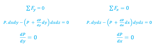
Relative Equilibrium of Fluids:
If
a fluid is contained in a vessel which is at rest, or moving with constant
linear velocity, it is not affected by the motion of the vessel; but if the
container is given a continuous acceleration, this will be transmitted to the
fluid and affect the pressure distribution in it. Since the fluid remains at
rest relative to the container, there is no relative motion of the particles of
the fluid and, therefore, no shear stresses, fluid pressure being everywhere
normal to the surface on which it acts. Under these conditions the fluid is
said to be in relative equilibrium.
2.1.0 Pressure:
For a static fluid, the only stress is the normal
stress since by definition a fluid subjected to a shear stress must deform and
undergo motion. Normal stresses are referred to as pressure P. For
the general case, the stress on a fluid element or at a point is a tensor.
F = normal force acting over A.
As already noted, p is a scalar, which can be easily
demonstrated by considering the equilibrium of forces on a wedge-shaped fluid
element.
2.1.1 Pressure Transmission:
Pascal's law: in a closed system, a pressure change
produced at one point in the system is transmitted throughout the entire system.
v
Absolute Pressure, Gage Pressure, and Vacuum
For PA > Pa
, Pg = PA - Pa
= gage pressure.
For PA < Pa
, Pvac = -Pg
= Pa - PA = vacuum pressure.
2.1.2 Pressure Variation
with Elevation:
Basic Differential Equation
For a
static fluid, pressure varies only with elevation within the fluid. This can be
shown by consideration of equilibrium of forces on a fluid element.
Newton's law (momentum principle) applied to a static fluid:
Basic equation for pressure
variation with elevation.
For a static fluid, the pressure only varies with
elevation z and is constant in horizontal xy planes. The basic
equation for pressure variation with elevation can be integrated depending on
whether
= constant or
=
(z),
i.e., whether the fluid is incompressible (liquid or low-speed gas) or
compressible (high-speed gas) since g
constant.
2.1.3 Pressure with Depth:
Suppose
we had an object submerged in water with the top part touching the atmosphere.
If we were to draw an FBD for this object we would have three forces:
1. The weight of the object.
2. The force of the atmosphere pressing down.
3. The force of the water
pressing up.
But
recall, pressure is force per unit area. So if we solve for force we can insert
our new equation in.
Where,
P = Absolute Pressure.
2.1.4 Pressure Measurements:
Pressure is an important variable in fluid mechanics and
many instruments have been devised for its measurement. Many devices are based
on hydrostatics such as barometers and manometers, i.e., determine pressure
through measurement of a column (or columns) of a liquid using the pressure
variation with elevation equation for an incompressible fluid.
More
modern devices include Bourdon-Tube Gage (mechanical device based on deflection
of a spring) and pressure transducers (based on deflection of a flexible
diaphragm/membrane). The deflection can be monitored by a strain gage such that
voltage output is p across diaphragm, which enables electronic data acquisition
with computers.
2.1.5 Manometer:
A change in elevation (Z2
– Z1) of a liquid is equivalent to a change in pressure (P2
– P1) / γ. Thus a static column of one or more liquids can be used
to measure differences between two points. Such a device is called a manometer.
If multiple fluids are used, we must change the specific weight in the equation
as move from one fluid to another. Fig. 2.8 illustrates the use of the equation
with a column of multiple fluids. The pressure change through each fluid is
calculated separately. If we wish to know the total change (P5 – P1),
we add successive changes (P2 – P1), (P3 – P2),
(P4 – P3), and (P5 – P4). The
intermediate values of P cancel, and we have, for the example of Fig
When calculating hydrostatic pressure
changes, engineers work instinctively by simply having the pressure increase
downward and decrease upward.
Thus,
without worrying too much about which point is Z1 and which is Z2,
the equation simply increases or decreases the pressure according to whether
one is moving down or up. For example, Equ above could be written in the
following “multiple increase” mode:
That is, keep adding on pressure increments as you
move down through the layered fluid. A different application is a manometer,
which involves both “up” and “down” calculations.
Fig 19
The
Fig.19 shows a simple
manometer for measuring PA in a closed chamber relative to
atmospheric pressure P0, in other words, measuring gage (relative)
pressure. The chamber fluid
is combined with a second fluid
,
perhaps for two reasons:
1) To protect
the environment from a corrosive chamber fluid or,
2) Because a heavier fluid
will keep Z2 small and the open
tube can be shorter.
One can apply the basic
hydrostatic 2nd Equ. Or, more simply, one can begin at A, apply 1st Equ.“down”
to Z1, jump across fluid 2 to the same pressure P1, and
then use 2nd Equ “up” to level Z2:
The physical reason that we can “jump across” at
section 1 in that a continuous length of the same fluid connects these two
elevations. The hydrostatic relation requires this equality as a form of
Pascal’s law: Any two points at the same elevation in a continuous mass of the
same static fluid will be at the same pressure. This idea of jumping across to
equal pressures facilitates multiple-fluid problems.
2.1.6 Manometer:
Atmospheric
pressure is measured by a device called a Barometer. Thus, the atmospheric
pressure is often referred to as the barometric pressure. A force balance in
vertical direction gives:


No comments:
Post a Comment
Note: Only a member of this blog may post a comment.